
Wechat/Whatsapp:
+8618825874379
Wechat/Whatsapp:
+8618825874379
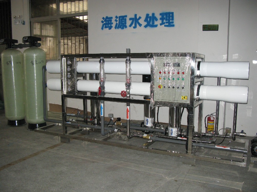
HYWATER Reverse Osmosis plant/system
What is the problem of reverse osmosis equipment when the desalination rate drops Decreases in salt rejection and permeate production are the most common failures in reverse osmosis equipment. Once performance degradation is found, the first step in solving the problem is to identify the location of the problem and find out the cause of the problem. The operating parameter record sheet can be used. Or some online measuring instruments to achieve. If system data is insufficient to determine the cause and take corrective action, one or more membrane elements must be removed from the system for analysis to determine the location of the leak. Step 1: Find the distribution law To do this, samples are taken from the permeate side of all pressure vessels to determine individual TDS, conductivity or other water quality related values. During the sampling process, the product water in other pressure vessels should be prevented from being mixed to affect the measurement results, and then the concentration of dissolved solid TDS in all the product water samples should be measured. In nanofiltration systems, analytical methods for the determination of sulfate ions or other related components must also be employed. The test results of all pressure vessel permeate samples in the same section should be in the same interval. Of course, it should be noted that from the first section to the second section, the average permeate water TDS or conductivity value should increase accordingly. This is because the second section has a The influent is due to the concentrated water in the first stage. In order to determine the leakage rate of the solute in all pressure vessels, the influent concentration of each section should also be determined. Salt leakage rate is the percentage of produced water concentration to influent water concentration, so high salt leakage rate may appear in the first or second stage, and may also appear in some pressure vessels. Step 2: Detect the membrane element If a pressure vessel exhibits a higher permeate concentration than other pressure vessels in the same section, the membrane element performance within that pressure vessel should be probed. The detection method uses a plastic pipe of about 1/4 inch diameter to insert into the water production center pipe of the entire membrane module. head. If the connection to the permeate main is not disconnected, ensure that permeate from other pressure vessels will not interfere with the detection. When the RO/NF system is operating under normal operating conditions, the initial shunted water sample from the pressure vessel permeate central pipe is not representative. Wait a few minutes for the probe pipe to be flushed, the system to reach equilibrium, and then from the probe The TDS value of the permeate water flowing out of the pipe can be measured by a hand-held instrument, and the data can be recorded, which can reflect the TDS value of the permeate water of the membrane element at this position. The detection tube should be pulled out 6 inches from the deepest point (varies according to different membrane shell brands) to measure the conductivity of the produced water at the adapter (commonly known as a grenade) between the pressure vessel end plate and the membrane element, and then pulled out 8 inches to measure the conductivity. The permeate conductance at this location, the distribution law of permeate conductance obtained at this interval is shown in the figure above, and the sampling location interval must be 8 inches (200mm), so that the fifth permeate sampling in each group corresponds to two Internal joints between components. This measurement method measures multiple data points per component and checks all nipples and adapter "O" rings at the same time. Therefore, marks should be made on the sampling tube during measurement to quickly find the desired sampling position. From the inlet end of the vessel to the concentrated water end, the conductivity distribution of normal produced water shows an increasing trend of equilibrium. If there is an abnormal deviation from this distribution law, the location of the high salt leakage rate fault can be determined. The "O" ring fault generally reflects a sudden change in the conductivity curve corresponding to the inner joint or adapter. A significant increase in conductivity at other locations indicates that the corresponding membrane element is faulty. More inquiries related to reverse osmosis equipment please contact: Mob& Wechat& WhatsApp: (+86)13544774483 Email: sales010@water-sy.com We will provide high-quality, all-round comprehensive professional services for project consulting, system design, manufacturing, installation and commissioning, personnel training, etc

